 |
||
|
|
||
|
|
 INTERVIEW Watch an interview with Josh. Choose your connection speed: 56K 300K PHOTO ALBUM See how Josh built the Bayonne Bridge Model. |
THE
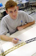
STRUCTURES LAB Joshua (“Josh”) White, a junior in the civil engineering department, is also pursuing a certificate in the Architecture and Engineering program. The opportunity to follow a course of study that includes both engineering courses and architecture studios was one of the major reasons he came to Princeton from his home in Virginia. Josh is a National Merit Scholar and Eagle Scout who has traveled to nineteen countries, although he has never been to Switzerland. Luckily he only has to go to New York City to see Ammann’s bridges. Josh and Joe Vocaturo built models of Othmar Ammann’s Bayonne and George Washington Bridges. For the Bayonne, he began by creating scale drawings. From these he generated a three-dimensional computer model using the program Pro/Engineer. With the help of Glenn Northey from the Department of Mechanical and Aerospace Engineering, he then programmed the CNC machine to use codes generated by Pro/Engineer to cut the side pieces of the arch. After soldering the two planar sides of the arch together, he joined the two sides with horizontal truss pieces. The difficult part was installing the V-shaped truss pieces, because each of these is a different size and had to be individually fitted. Joe Vocaturo fabricated a fixture, however, that allowed Joe to quickly and precisely mark brass elements, which he could then cut to the precise size and shape needed. The construction of the George Washington Bridge model
began with a design for the towers. For this project, he decided to
use AutoCAD and the laser cutter to cut Plexiglas® pieces. The towers
are made of flat pieces bonded together. The main cables are very thin
steel tubes that are pinned to an aluminum fixture at the top of each
tower. The ends of the tubes are threaded and have tiny screws in them
that allow for delicate adjustment of the tension in the main cables
to ensure that they take on the proper shape. The deck is made of a
foam composite—essentially it is a lightweight foam core with
a tough outer skin. Ted Griffith fabricated another fixture that held
the bridge during assembly. The bridge was actually built upside down.
Ted’s fixture offered a number of advantages. First, it ensured
that all of the components would line up properly. Second, it held the
cables in shape during assembly. Third, it supported the deck while
the suspender cables were being attached. Finally, because the bridge
was held upside down, it allowed for easy access to all of the connections
on the underside of the deck and cables.
GLOSSARY
I ACKNOWLEDGMENTS
I RELATED
LINKS |
|
